
Measuring Flatness: Techniques and Methods for Assessing Surface Planarity
Measuring the flatness of a surface is an essential requirement in many industrial and manufacturing processes. Accurate measurements ensure the optimal performance of components and products, reducing the risk of failure and improving quality. The flatness of a surface can be affected by various factors such as the manufacturing process, material properties, and environmental conditions.
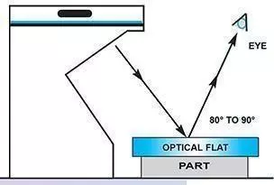
One of the most common methods used in the Flat Lapping sector to measure flatness is by using a Monochromatic Sodium light unit and an Optical Flat. An Optical Flat is a high-precision glass or quartz flat surface that acts as a reference plane. When a monochromatic light source, such as a Sodium light unit, is directed onto the Optical Flat, the light is reflected and forms a series of bright and dark fringes called light bands.
Diamond lapping processes are ideal for producing reflective surfaces that can be measured for flatness using this method directly after the lapping operation. This enables the production of high-precision components and products with excellent flatness. Other methods for measuring flatness include laser interferometry, profilometry, and tactile methods, each with its own advantages and limitations. However, the Monochromatic Sodium light unit and Optical Flat method remain a popular choice for measuring flatness in many industries.
What are light bands?
Isaac Newton discovered Light Bands in 1717 and investigated them. These bands are formed through the interference of light between two surfaces. If a monochromatic light source is employed, the phenomenon can be utilized to determine the levelness of a component. However, the surface of the component must be reflective for the light bands to appear.
The light bands are made up of a bright and dark fringe, which correspond to the wavelength of the monochromatic light. In the case of a Sodium light source, the wavelength is equal to 589nm. When checking parts for flatness, it is only the dark bands that are counted. As this is half the total fringe, each dark band equals 0.0000116 inches (294nm). This method provides extremely precise measurements, more accurate than most CMM (Coordinate Measuring Machine) measurements, in an economical way.
Flatness Calculator
Precision Surface Flatness Analysis using Light Band Patterns
| Surface geometry | 1 Light band 0.0000114 in | 2 Light bands 0.0000228 in | 3 Light bands 0.0000343 in | 9 Light bands 0.0001028 in | |
|---|---|---|---|---|---|
Convex or ConcaveSurface parallel to flatSymmetrical Pattern |  | 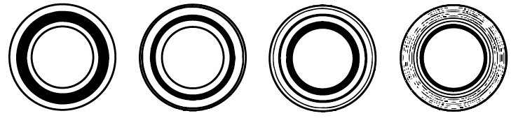 | |||
ConvexWith concave surface band will curve in opposite directionNon-Symmetrical Pattern | 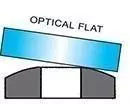 | 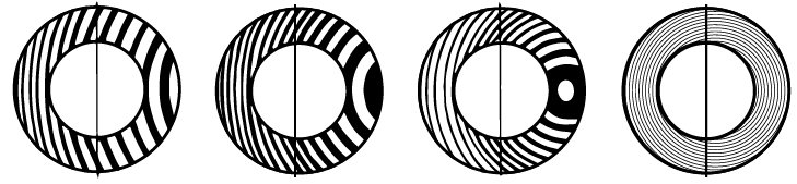 | |||
CylindricalConvex or ConcaveSymmetrical Pattern |  | 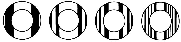 | |||
Saddle ShapedSymmetrical Pattern |  |  | |||
Analyzing Interference Fringes with Optical Flat for Accurate Flatness Measurement
To read light bands with an Optical Flat, the first step is to ensure that both the surfaces of the component and the optical flat are clean. Use a lens tissue or soft lint-free cloth to clean both surfaces thoroughly. It is essential to make sure that there are no contaminants or particles on the surfaces, as this can cause inaccuracies in the measurement.
Next, carefully place the optical flat on top of the component, ensuring that it is not slid across the surface. As the optical flat and component come together, lines will appear through the flat. These lines are known as interference fringes or light bands and are an indication of the level the component's surface has risen or fallen in relation to the optical flat.
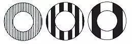
To obtain a line pattern, manipulate the optical flat until the interference fringes are visible. The line pattern is essential as it allows for the correct interpretation of the level of flatness. It is worth noting that the patterns may vary depending on the type of component and the surface finish. Typically, there will be a series of lines that are dark and light, with the dark lines representing the areas of the surface that are lower than the optical flat, and the light lines indicating the higher areas.
To accurately measure the level of flatness, count the number of dark lines and multiply this by the width of the light band. This will give the height difference between the component's surface and the optical flat, expressed in inches.
Interpreting Interference Fringes for Precise Flatness Assessment: Analyzing Light Band Readings
Lapping plate flatness
CONVEX
If the workpiece is convex, the ring pattern will move towards finger pressure, and the lapping plate will be concave.
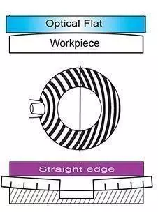
Lapping plate concave
To correct this condition, the control rings must be moved to the outside of the plate.CONCAVE
If the workpiece is concave, the ring pattern will move away from finger pressure, and the lapping plate will be convex.
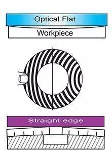
Lapping plate convex
The control rings must be moved to the inside of the plate to correct this conditionIt is worth noting that the flatness of a surface is determined by the straight parallel bands and not the width of the light band. Therefore, to accurately measure the flatness of a surface, it is important to focus on the straight parallel bands and not the light band's width.
Surface Finish Measurements: Understanding Ra and Rt Parameters for Roughness Analysis
A variety of material removal processes are used to produce surfaces, which can be split into three components: roughness, waviness, and form. The resulting total geometry is defined by these components.
Basic parameters
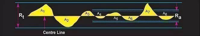
Several parameters are used to measure the surface finish, including Ra and Rt. The centerline separates the areas such that A1 + A3 + ............ A7 = A2 + A4 + ............ A8. Ra and Rt are the most commonly used parameters for surface finish measurements.
Ra is widely recognized as the most frequently used international parameter for roughness. It is calculated as the arithmetic mean of the deviations of the roughness profile from the mean line.
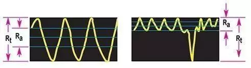
Rt is the maximum peak-to-valley height of the profile over the measured length. Measurements are typically reported in micro inches (μin), where 40 micro inches is approximately equal to 1 micron.
Examples of Ra and Rt
Surface finish or texture on a drawing can be indicated using various symbols, including:

Symbol A This symbol is used to specify the maximum roughness value in Ra micro inches.
Symbol B This symbol is used to specify both the maximum and minimum roughness values.
Symbol C This symbol is used to specify the maximum roughness value along with the finishing process.
Equipment for measuring flatness
Kemet Optical Flats

Produced from Quartz, Kemet Optical Flats are available in single and double sided, 1/4 light band or 1/10 light band accuracy. Standard sizes from 1" up to 12" diameter.
Kemet Monochromatic Light

Produces clear flatness readings when used with Kemet Optical Flats. The compact designed Light is easily transportable and uses a sodium long-life sodium light source. Supplied with a flatness reading interpretation chart.
Kemet Flatness Gauges
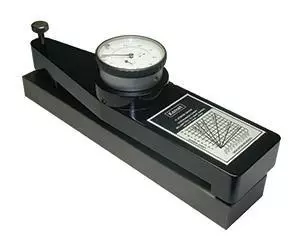
The Kemet Flatness Gauge is used to monitor a lapping plate's flatness and to give an indication of the flatness the plate will produce on a given part size.
